← back to the build document · the roof frame · the standard brackets · the rack for the lengthwise layout · the design history · mounting the a/c & fan · building the a/c & fan frames · the build order · the interior frame · the parts list · the build manual · the solar book, distilled
Building the roof rack
Same rack, simpler corners. Gutter side rails, raised supports, crossbars above the crown — but the supports are now catalog strut fittings bolted to slotted members instead of plates and gussets cut to order. The brackets themselves are on the hardware page →
The layout is now decided — three modules lengthwise, two down the driver side, the third between the A/C and the fan on the curb side. The rack drawn to that layout, with the crossbar stations and the quantified parts list, is on its own page: the rack for the lengthwise layout →
This page is the order the work happens in. The rack carries solar only — the A/C and the fan seal at roof level and are supported by a separate internal frame, so the rack's job around them is to stay clear.
The stack, top to bottom
conceptual topology — what connects to what, not a load-approved assembly
- 1 · existing gutter attachmentThe factory roof interface. Capacity and what sits behind each point are still unverified — that is a measurement and documentation job, and it is the one genuinely open item. It does not block picking the fittings.
- 2 · fore-aft side railSlotted channel down each gutter line, cut to measured length. Spreads load into several points, and lets a support land anywhere along it.
- 3 · catalog gusseted fittingP2484 into the rail through channel nuts — the braced base of each support, in one stocked piece.
- 4 · uprightChannel or 15-series extrusion, cut to whatever rise the roof crown actually needs.
- 5 · catalog upper fittingP2484 again at the top corner, or a lighter fitting where the load case allows it.
- 6 · matched crossbarSlotted, same family as the fittings — so both the fittings and the module hardware have something to grip. Why this replaces the plain tube →
- 7 · module hardwareWhatever the Jinko JKM405M-72HL-V manual approves, in the size it specifies. Three modules owned, 148.8 lb of glass.
What the stack looks like
conceptual assembly · not load-rated, not a vehicle connection, not a locked design
Two sheets from the catalog parts pack: one corner close up, and the same parts in context over the roof. The parts themselves are on sheet 01.
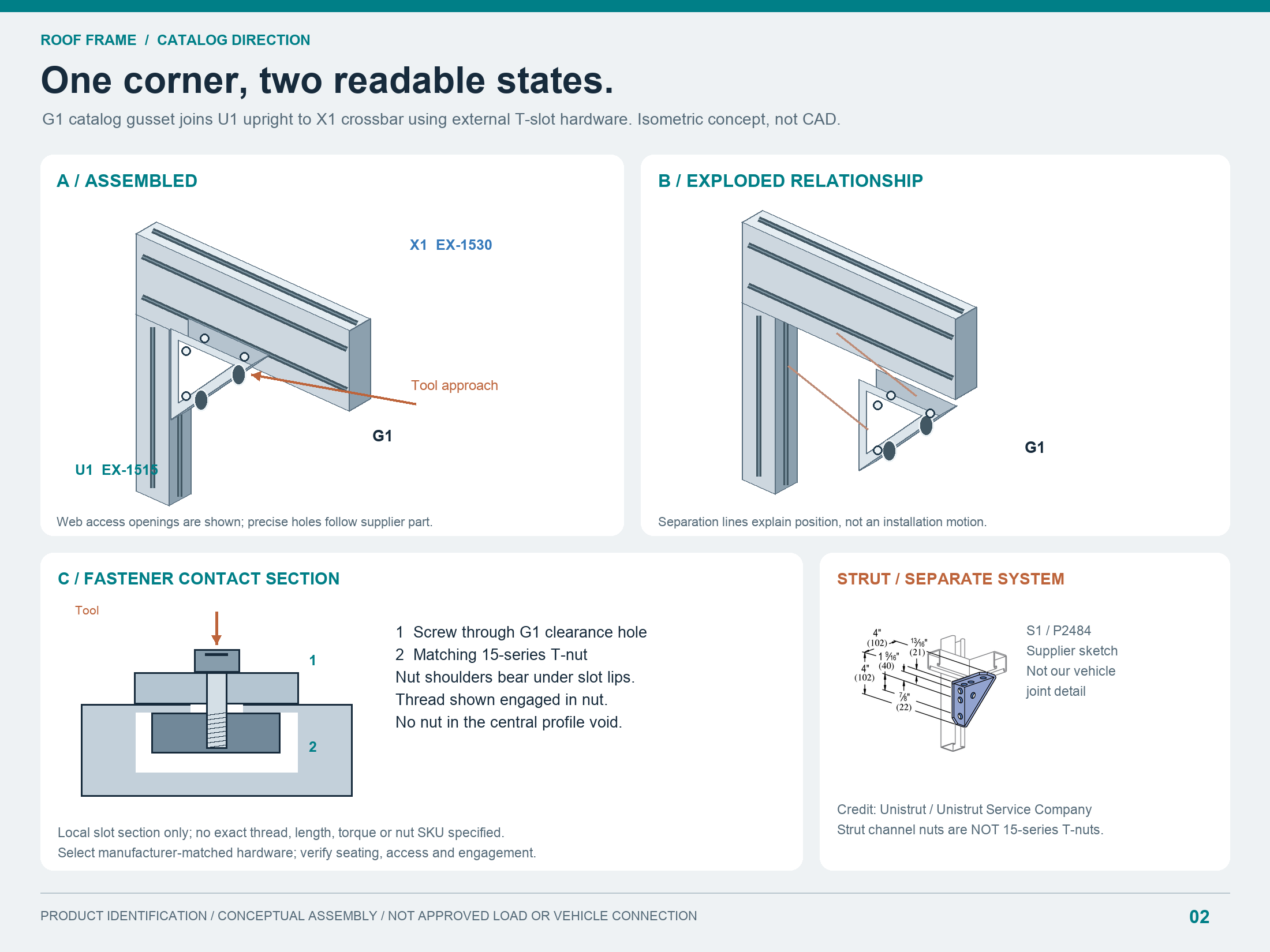
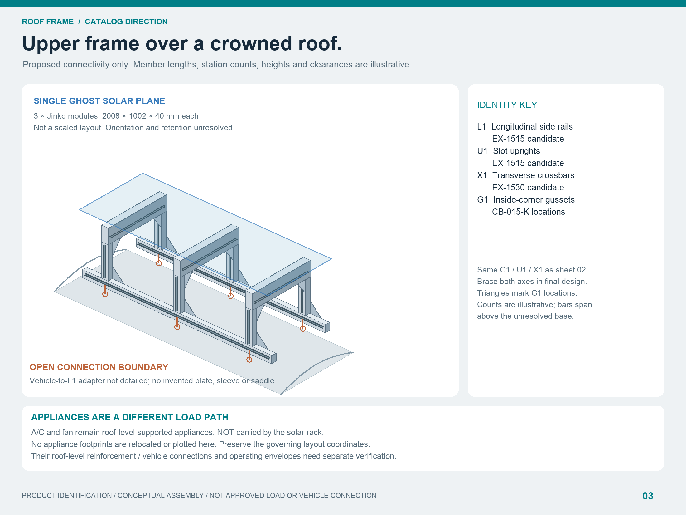
All three sheets: the catalog parts packet (PDF, 3 pages) →. Drawn by Mickey; supplier photographs credited on the sheets.
The build order
measure, then select, then order, then assemble · nothing is bought until stage 3
Stage 1 — measure the vanrecording only · nothing bought, nothing touched
- The attachment interface. What is actually up there, how many points per side, spacing, thread projection where studs are involved. Photograph both rear gutter ends — there is a drain filter at the rear in the documented owner build, and it decides where the last point can land. produces: rail length and the support stations
- The envelope. Across-van distance between the two attachment lines, roof crown height above the attachment line at each intended support, and every existing rib, penetration and obstruction. produces: crossbar length and the upright rise
- The appliance footprints. A/C and fan positions, the fan lid's full travel, airflow paths and service access. They are not on this rack, but they decide where a crossbar cannot go. produces: the keep-out zones
- The module's own requirements. The JKM405M-72HL-V installation manual — approved clamp zones or approved mounting holes, with the bolt size and torque from the table for this exact module. produces: the only thing that selects panel hardware, and whether the crossbar spacing works
Stage 2 — settle the family and the sectionsa decision, not a purchase
- Pick one fastener family and stay in it. Strut channel with P2484 fittings and channel nuts, or 15-series extrusion with T-slot gussets and T-nuts. The two do not mix — different nut bodies, different slots. The shortlist for both →
- Make the crossbar slotted. A plain closed tube gives a fitting nothing to bolt into, and the size-matched clamp that would fix that is not selected. Going slotted is what lets the whole frame be bolt-together catalog parts.
- Check the sections against the real numbers. Span, the 148.8 lb of glass, highway uplift, loaded deflection, and the rise from stage 1. Note the strut load tables apply to carbon and stainless steel, not to the aluminium channel — aluminium needs its own data. produces: sections, wall thicknesses, fitting count and the cut lengths
Stage 3 — quote, order, check on arrivalthe first stage that spends money
- Get the aluminium channel quoted properly. The aluminium variants show $0.00 on the supplier page — that is a blank, not a price, and the visible $64.90 is pregalvanized steel. Ask for the aluminium quote, the cut-to-length service, and the fitting cut sheets while you are at it.
- Confirm the fitting actually overlaps the upright. P2484's leg lengths are not on the product page. Pull the cut sheet before assuming it fits a short riser.
- Order fittings, nuts, bolts and washers as a matched set, plus corrosion isolation if steel fittings are going onto aluminium channel. Check what arrives against the packing list before anything goes on the van.
Stage 4 — assemblebench first, then up on the van
- Build one complete support on the bench. Fitting, upright, upper fitting. Check it square, confirm every bolt engages and every channel nut is actually turned under the lips. One support proves the geometry before you make five more.
- Set the gutter attachments one point at a time, then land both side rails and confirm gutter drainage is unobstructed before anything sits on top.
- Bolt the supports to the rails, then the crossbars on. Multiple separated fasteners per support — two fasteners apart resist rotation, one does not. Then check crown clearance with the rack loaded; an empty parked van is the easy case.
- Mount the modules with their approved hardware. Lift glass by the frame, never by a corner or the glass. Corrosion isolation goes in as you go, not as a later fix, along with cable clips, strain relief and end caps.
- Every joint gets a named locking method and a recorded torque. Witness marks are an inspection aid, not a locking device.
Stage 5 — commission, then keep looking at itongoing, permanently
- Function-check the array under load, and confirm nothing fouls the fan lid through its full travel or blocks A/C airflow.
- Re-check fasteners after the first loaded miles, then on a set interval.
- Scheduled visual inspection, permanently. Module faces and backs where reachable, connectors, wiring, mounts, corrosion, any sign of movement. Controller output is not the check — see the service history below.
What one year and 10,000 miles taught the owner who reported back
source: BrightDrop Forum, tiltable solar array — thread 375 → (FumelessCamper, posts #1, #2, #6, #11, #20, #24 and #27)
This is the owner build on this platform with reported service history behind it. It is a custom-fabricated rack, so its construction is not the direction any more — but three of its findings are about operating an array on a moving van, and those transfer to a catalog rack unchanged.
For context: nine 130 W flexible panels, 72 lb total, corrugated so the pre-bend adds stiffness, all weight on the side rails and none on the roof, with a 0.25″ gap between the crossmembers and the roof.
- Every connection needs a specified retention method. A different contributor in the same thread — running a tilting glass-panel assembly, not FumelessCamper's rack — had a ½″ × 3″ pin come out at 60+ mph on the interstate and watched a panel start bouncing. He moved to ball-lock pins and doubled the quantity. Nothing about that says FumelessCamper's hardware failed; what it says is that “locking hardware as appropriate” is not a specification. On a catalog rack that means using the manufacturer's specified locking system and torque at every joint, and checking that the manual actually gives you one.
- Mechanical clearance and panel ventilation are different requirements. The 0.25″ figure is crossmember-to-roof — a mechanical dimension. Panel-underside ventilation and material temperature limits are separate and a riser height does not close them. After a year and 10,000 miles two of this owner's cells failed and running the array afterwards produced a strong burning-plastic smell; his own read was “Important to have that airgap underneath, and perhaps my gap is too small. But even then, fire can spread.” That is a suspicion, not a confirmed cause — no air gap on this build gets called a fire gap or credited with preventing fire spread.
- The failure was invisible except by eye. “Merely through visual observation. I could not see any drop in production or any indicator of failure other than by looking. Which is somewhat disconcerting, since I do not often look at the roof.” Nothing at the charge controller flagged it. Controller output is not a substitute for climbing up and looking.
Still open
- The vehicle interface — whether a catalog product exists at all. Everything else waits on it.
- The attachment geometry: point count, spacing and thread projection both sides, and across-van distance between the two lines.
- Roof crown height above the attachment line, which decides riser rise — and whether either catalog rise is right.
- Crossbar width against a roof that has not been measured, and whether a fixed 72″ kit is usable.
- Whether an adapter and rail layer are needed, which falls out of crossbar positions against the module's approved mounting points.
- The exact Jinko-approved retention hardware, in the size its manual specifies.
- The limiting load rating across roof, attachment, bars and solar hardware, for road use.
- Ventilation and appliance airflow, separately from clearance.
- Quantities and the total — neither exists while the chain has a hole in it.
Status: the selection workflow is closed. The selection is not. No product on the hardware page is fit-confirmed for this van, and until stage 1 produces a manufacturer's answer this page is a way to run the decision, not a way to build the rack.
Superseded — the fabrication sequence
Until 2026-09-16 this page carried a twenty-one step, six-phase build guide for a custom rack: cut pipe spacers at each gutter stud, a bolted pedestal of cut plates, angles and gussets, and a crossbar tube captured in a fabricated saddle. Almost every part it consumed was one that had to be made, which is why the sequence went rather than being edited. Its operating lessons survived into the build order above; its construction did not.
The retired steps and their four concept drawings are archived: the fabrication sequence, retired →. Nothing in that archive is a product or a current instruction.