← back to the build document · the build order · the standard brackets · the roof frame · mounting the a/c & fan · building the a/c & fan frames · the front fairing · every part, pictured · what to buy · the a/c and fan frames · what the tape changes · the parts list
The rack for the lengthwise layout
The layout is decided: three Jinko modules lengthwise, two down the driver side, the third down the curb side between the A/C at the front and the fan at the rear. This page is the rack drawn to that layout — where every member sits, why the crossbars land where they do, and a parts list with quantities you can hand to a strut distributor. The hardware page picked the parts family; the build-order page is the sequence. This page is the geometry and the count.
The layout, to scale
top view, front at top · datasheet sizes on the assumed envelope · not a cut template
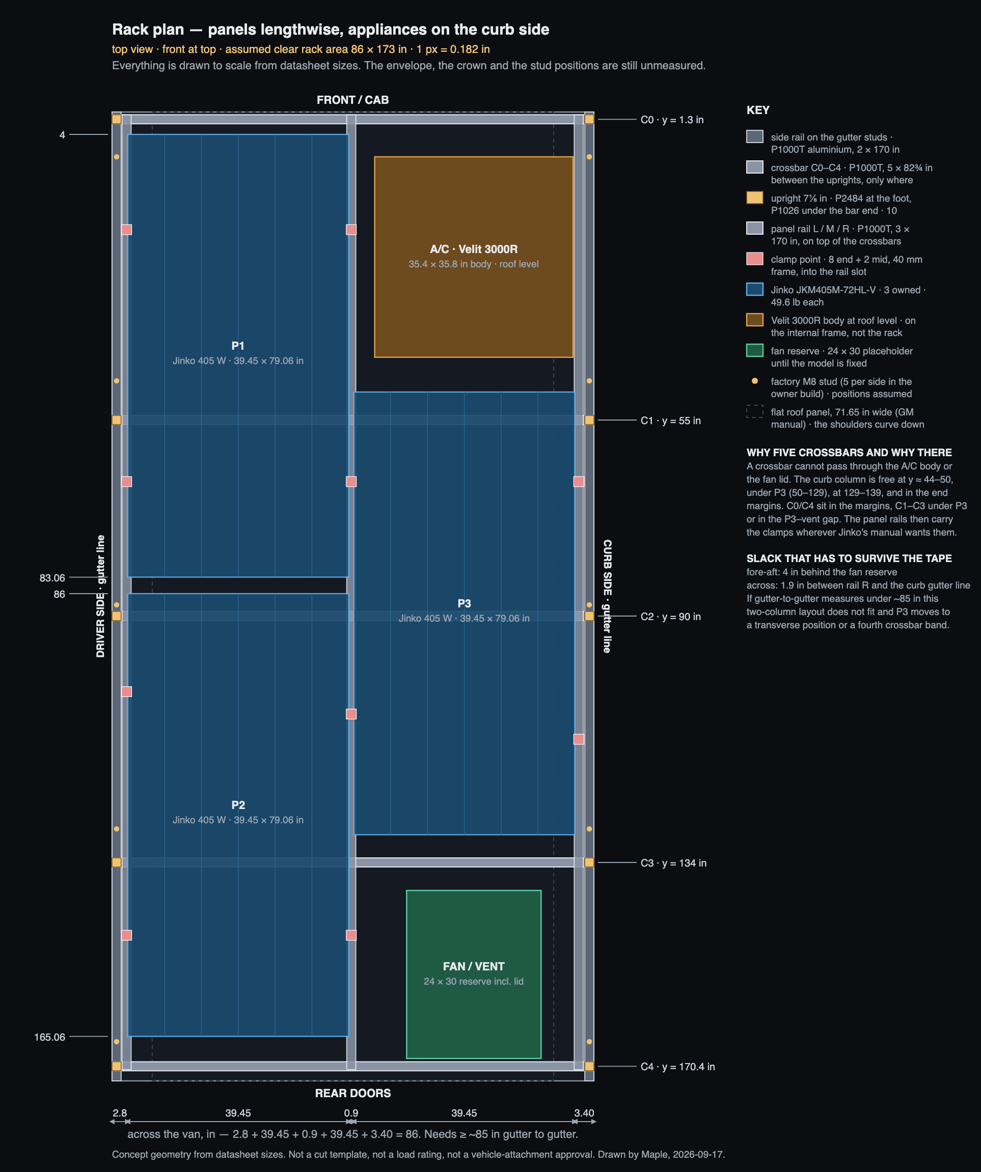
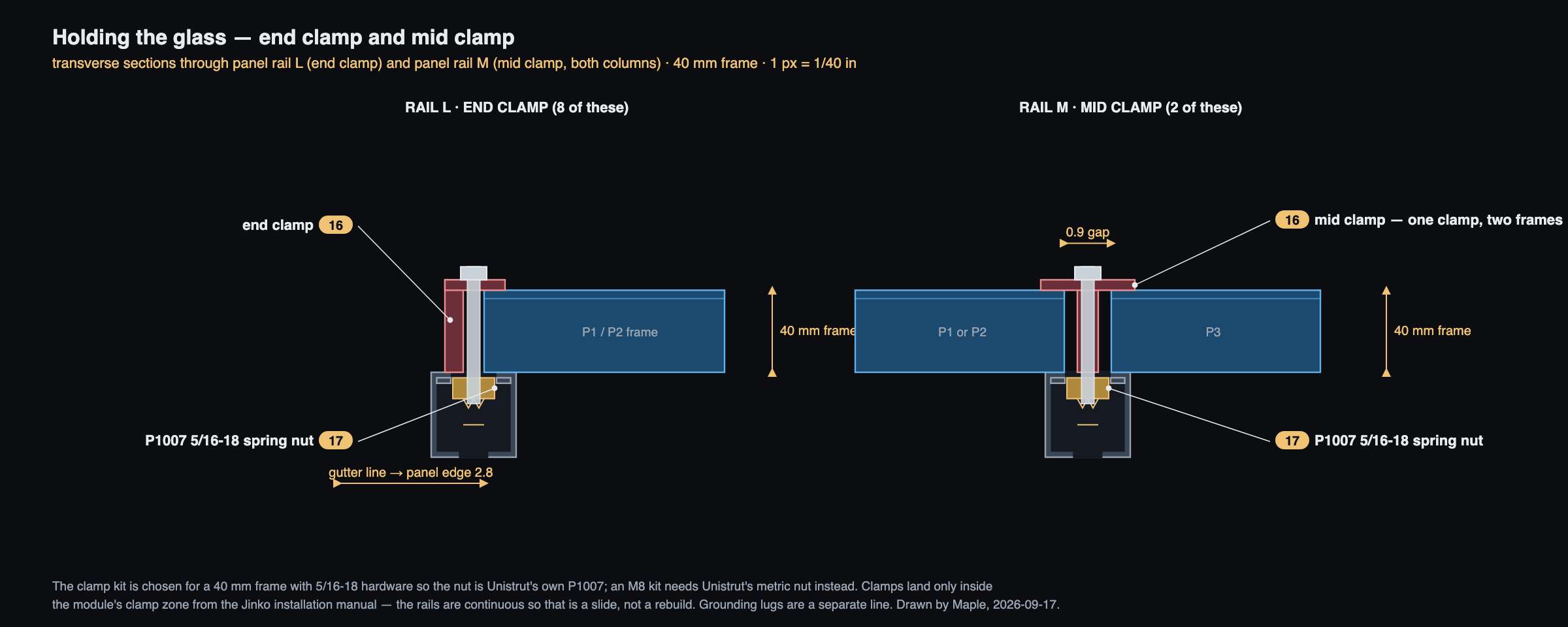
tools/rack_layout.py. Full size →Clamp points, by rail. Rail L (driver-side edge): end clamps at y ≈ 21, 66, 103.5 and 147. Rail M (between the columns): an end clamp at 21 and 147 where only P1 or P2 is present, and a mid clamp at 66 and 107.5 where the driver-side panel and P3 overlap — one clamp holds both frames. Rail R (curb-side edge): end clamps at 66 and 112. Ten clamps: eight end, two mid. The exact positions get checked against the clamp zone in the installation manual for this module before the clamps are ordered; the rails make that a slide, not a redesign.
How the stack goes together
transverse section at crossbar C2 (y = 90), looking aft · heights from the stud base
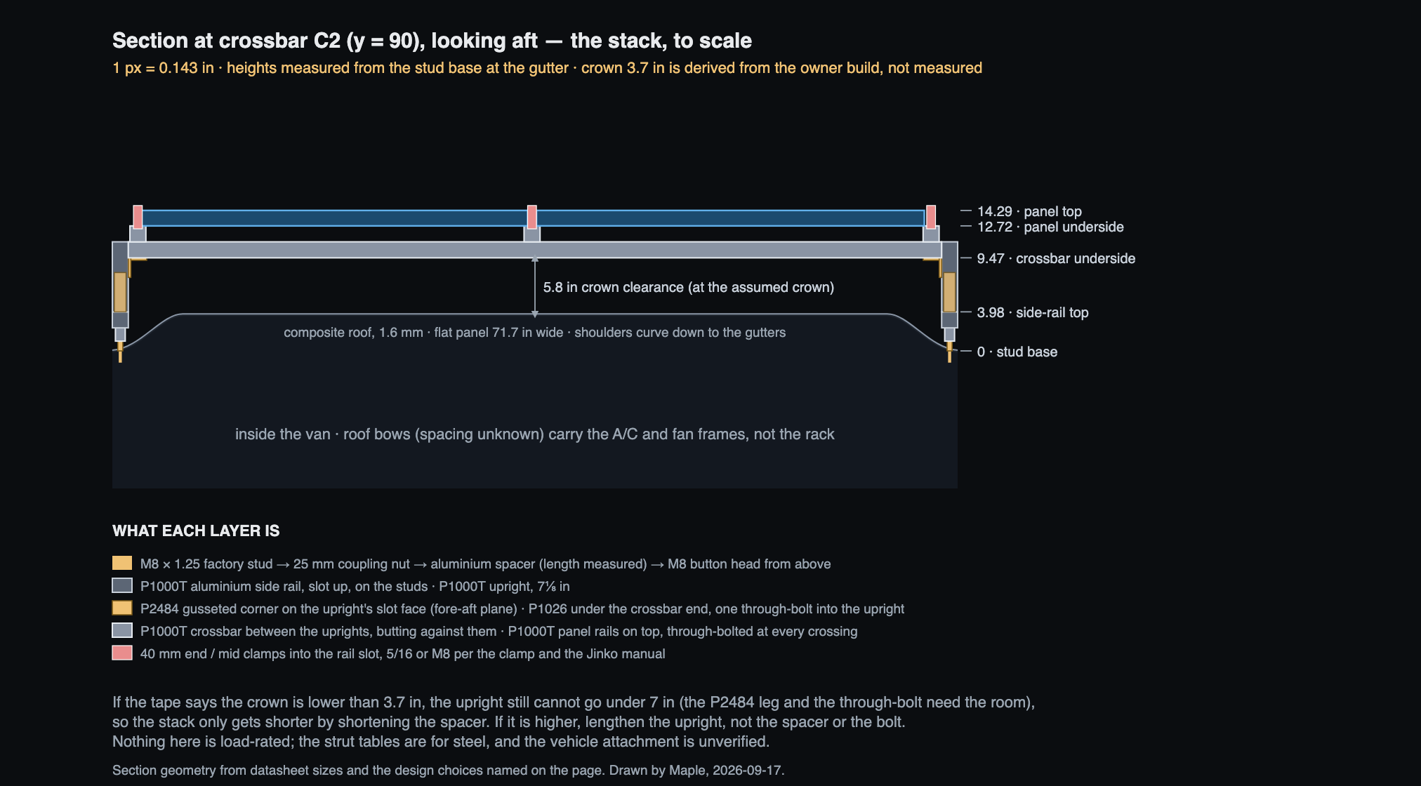
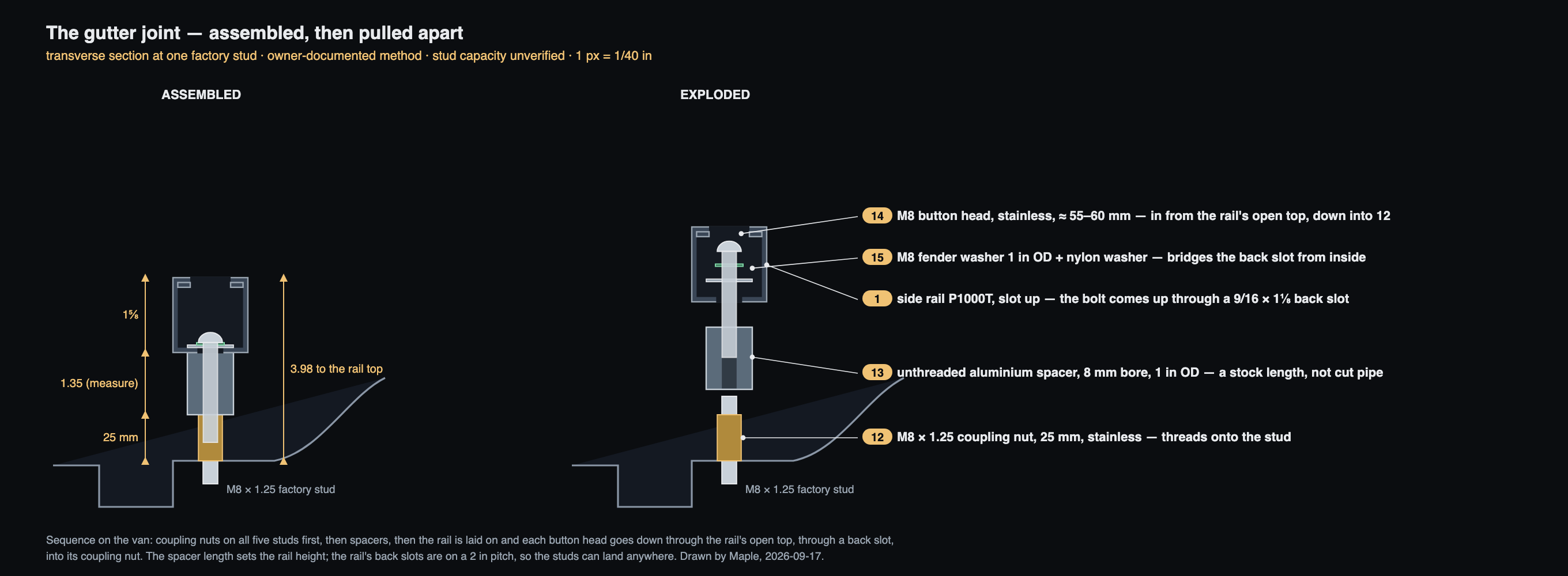
- 1 · gutterM8 × 1.25 factory stud → 25 mm coupling nut → aluminium spacer → M8 button-head from inside the channel, fender washer under the head. This is the owner-documented attachment on this platform, and it is still the one unverified link — stud capacity has no published number. The spacer is a catalog unthreaded spacer in the measured length, not a cut pipe.
- 2 · side railP1000T, 170 in, slot facing up, one per gutter line. The M8 bolts come up through its back slots (2 in pitch, so a stud can land anywhere). It spreads the rack into all five studs and lets the uprights sit at the crossbar stations rather than at the studs.
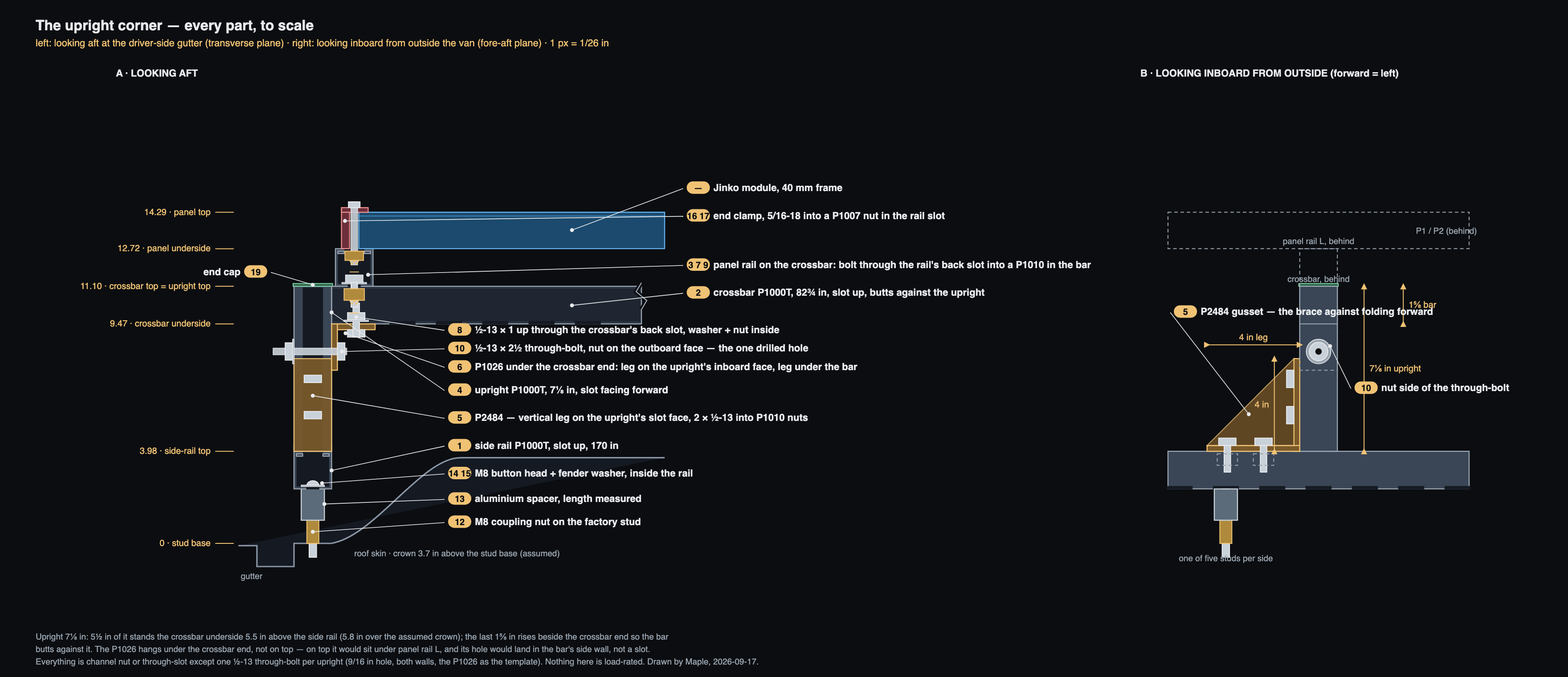
- 3 · bottom cornerP2484 on the upright's slot face, in the fore-aft plane: one 4 in leg down the upright, one 4 in leg along the side rail, two ½-13 bolts into P1010 channel nuts per leg. This is the braced corner that resists the rack trying to fold forward under braking or drag.
- 4 · uprightP1000T, 7⅛ in, slot facing forward. The bottom 4 in belong to the P2484 leg; the crossbar's underside lands 5½ in up; the last 1⅝ in rises beside the crossbar end so the bar butts against the upright instead of balancing on it. If the measured crown asks for more height, this is the member that gets longer — not the spacer, not the bolt.
- 5 · top cornerP1026 2-hole fitting, under the crossbar end: its 1⅞ in leg lies under the bar with a ½-13 bolt up through the bar's back slot (washer and nut inside the channel), its 2 in leg lies on the upright's inboard face with one ½-13 through-bolt across the upright — the one drilled hole on the rack, 9/16 in through both walls, the fitting as the template. The bar butts against the top 1⅝ in of the upright; the P1026 carries it and holds it against uplift. (On top of the bar the fitting would sit under panel rail L and its hole would land in the bar's side wall, not a slot — which is why it hangs underneath.)
- 6 · crossbarP1000T, 82¾ in (gutter-to-gutter minus two uprights, cut after measuring), slot facing up, five of them at y = 1.3, 55, 90, 134 and 170.4. The middle panel rail loads each one at mid-span; the two outer rails sit almost directly over the uprights.
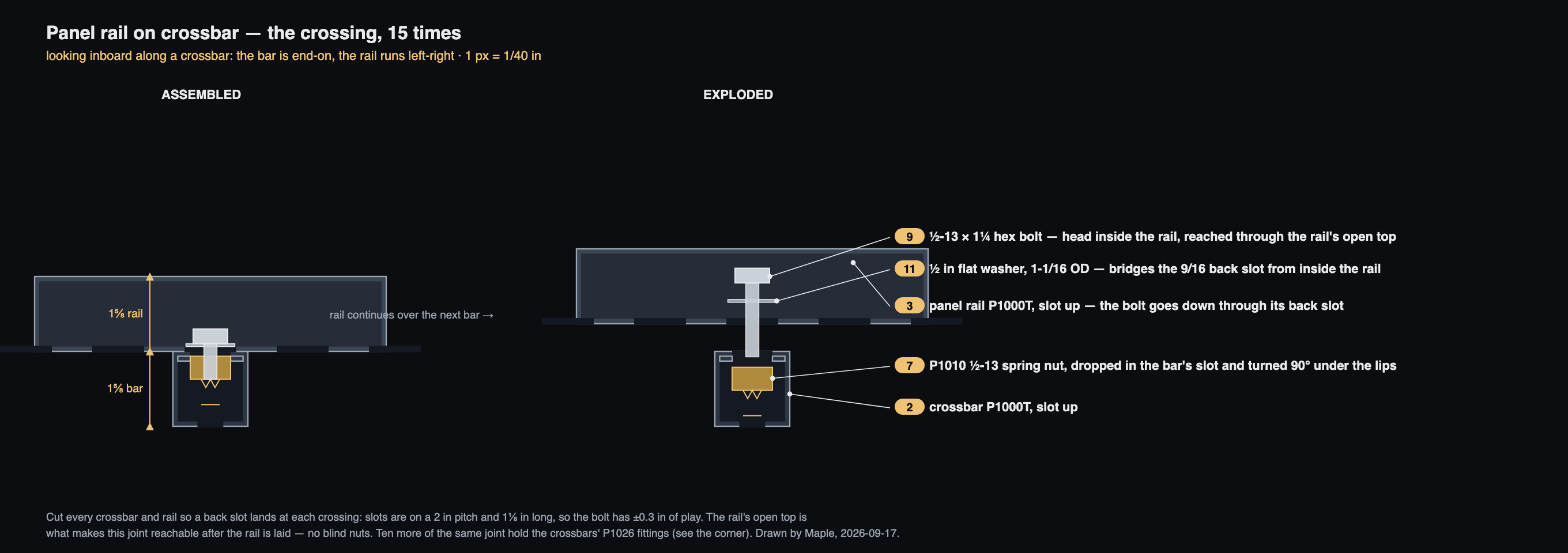
- 7 · panel rails and glassThree P1000T rails, 170 in, slot up, at x = 2.6, 42.7 and 83.4, through-bolted to every crossbar (bolt through the rail's back slot into a channel nut in the crossbar — 15 joints). Clamps for a 40 mm frame bolt into the rail slots. The modules lift by their frames and land last.
Every part, pictured — and how each one meets the next
the line numbers are the ones in the two tables below · photographs are the supplier's own product shots, drawings are to scale · nothing here is a rendering
Five joints make the whole rack. Every one of them is a catalog fitting or a bolt through a slot, and each drawing below shows the joint assembled and, where it helps, pulled apart with the parts numbered. Read the corner first — it is the joint that decides the upright length and the one place a hole gets drilled.
1 · The corner side rail → P2484 → upright → P1026 → crossbar → panel rail → clamp, in one place
2 · The gutter joint lines 1, 12–15 · five per side
3 · Panel rail on crossbar lines 2, 3, 7, 9, 11 · fifteen crossings
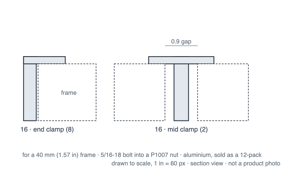
4 · Holding the glass lines 16, 17 · eight end clamps, two mid clamps
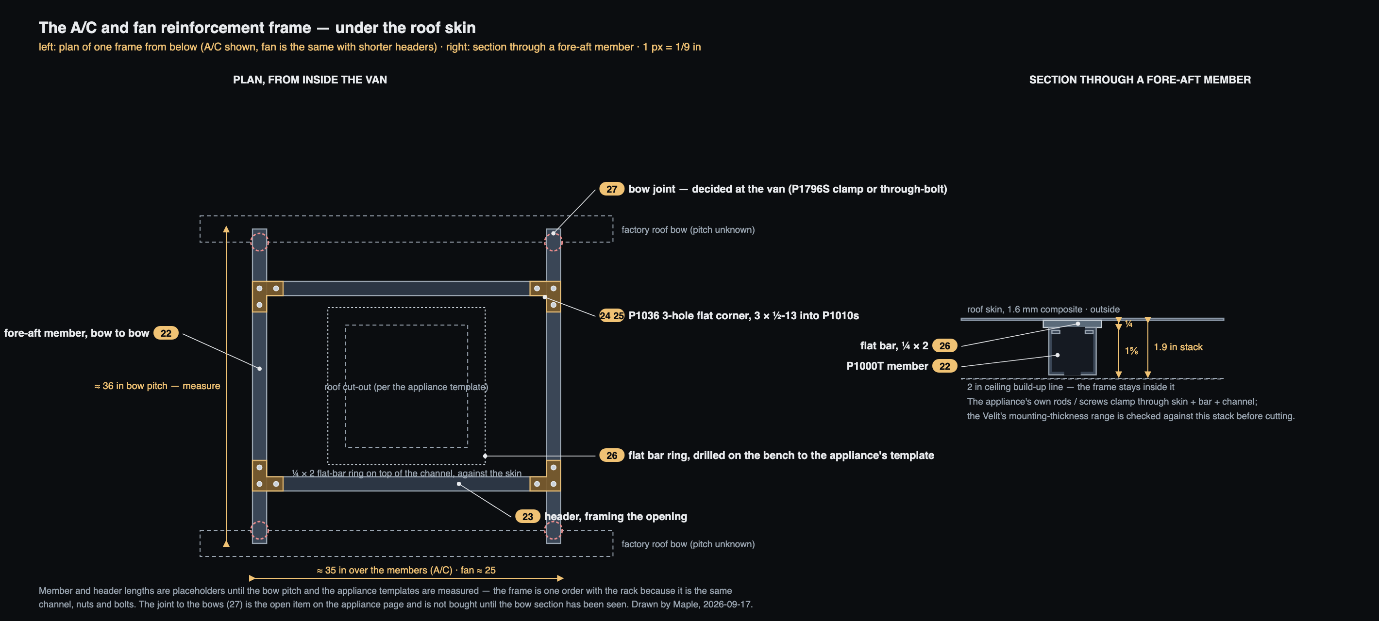
5 · The A/C and fan frame lines 22–27 · under the roof skin, same channel
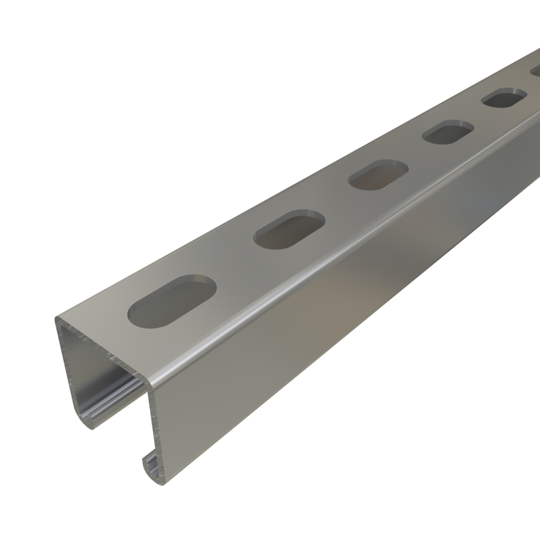
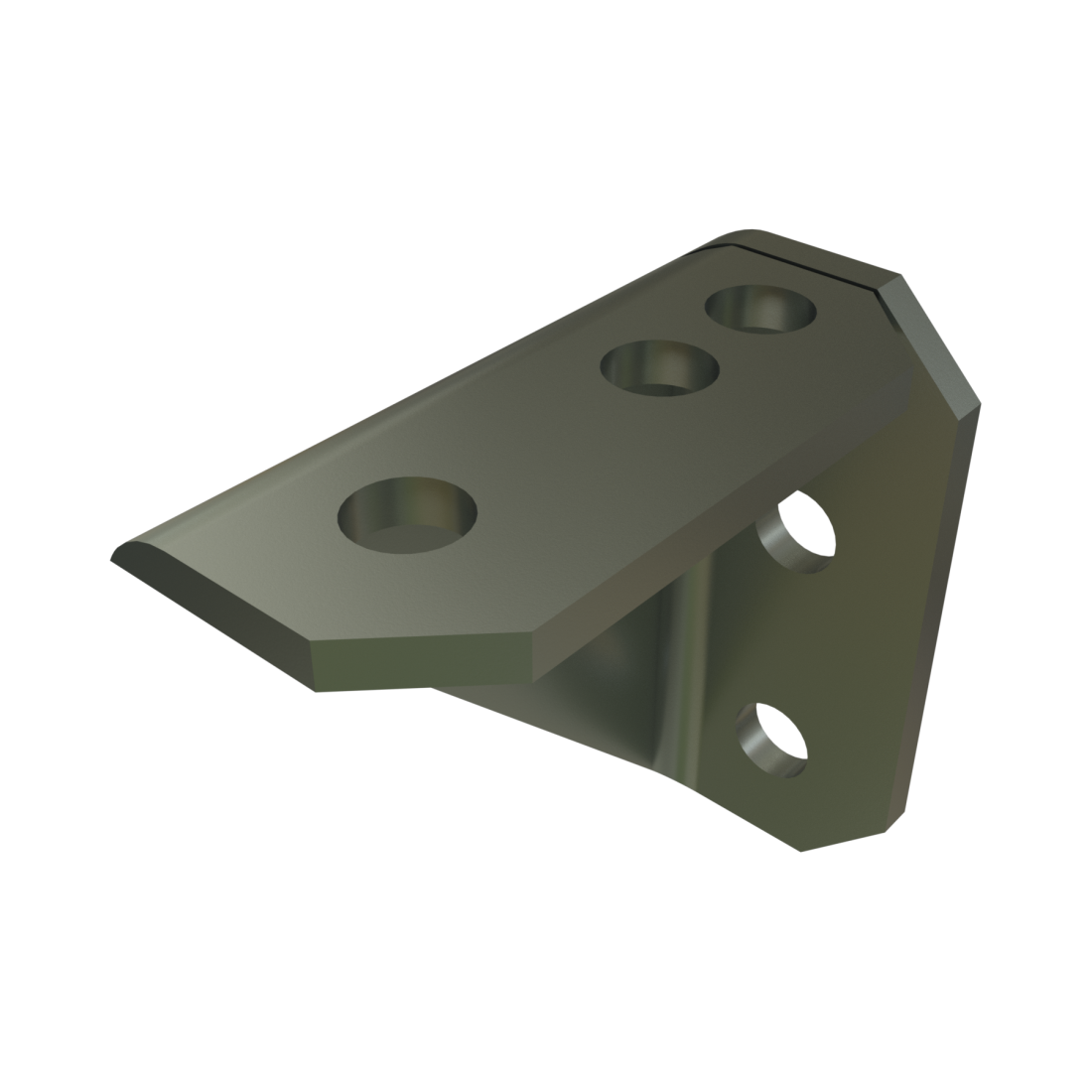
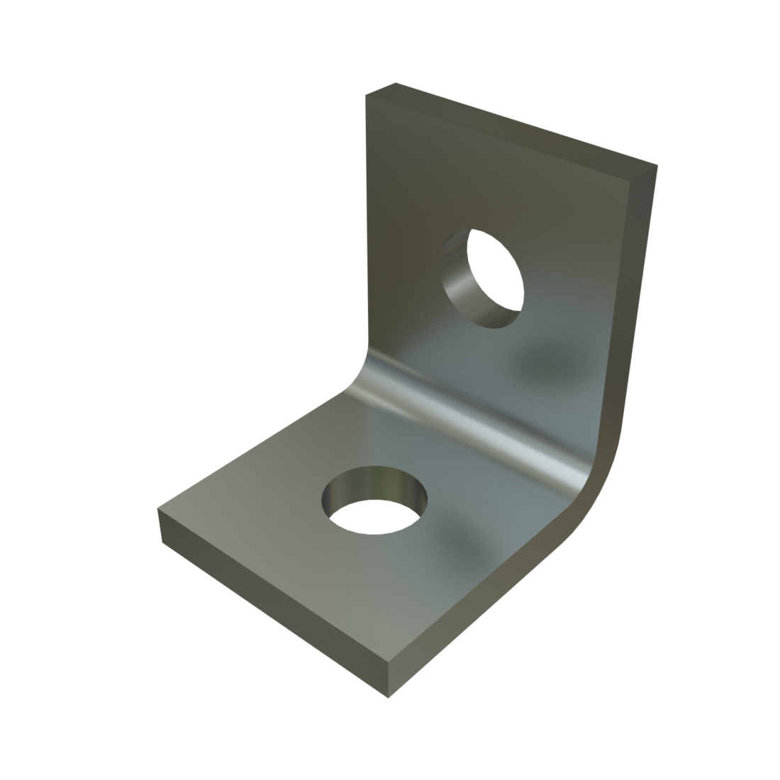
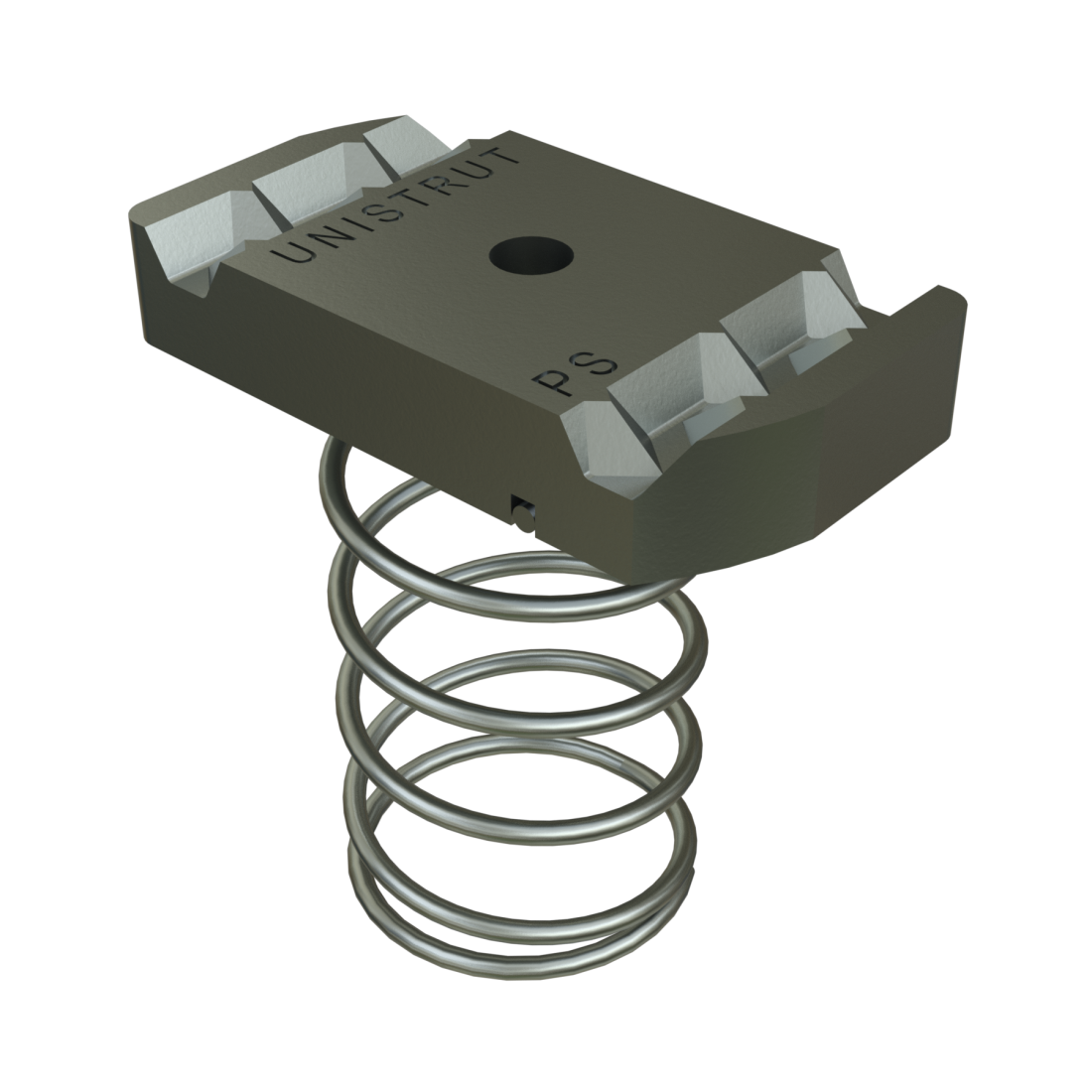
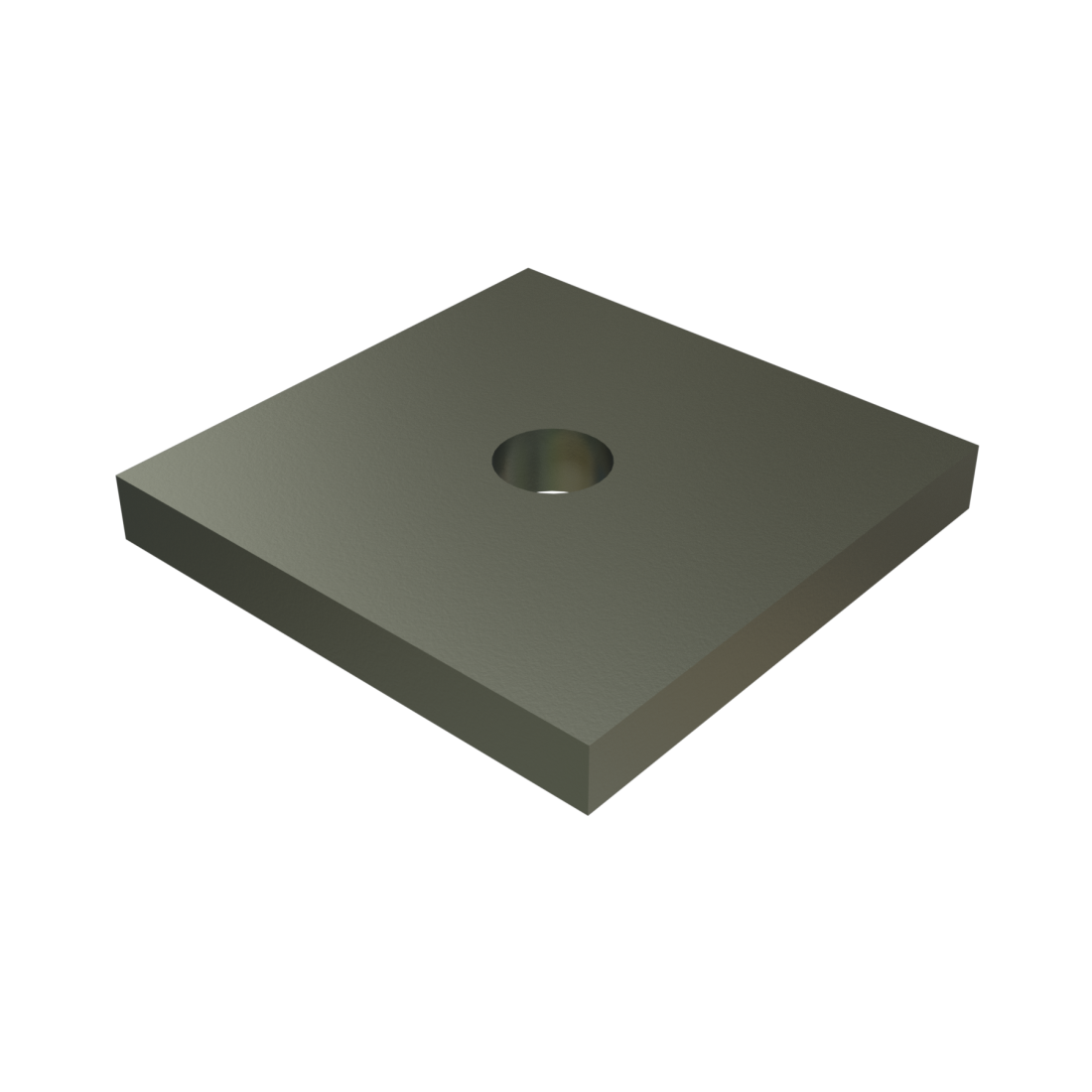
The parts themselves supplier product photographs where the part is a catalog item; to-scale drawings for the hardware-store pieces
What to buy — the rack
quantities for the drawing above · prices as displayed on the supplier pages at the 2026-09-16 check, not quotes · the aluminium channel is the one unpriced line and it will be the largest
| # | Part | Qty | Where it goes | Displayed price |
|---|---|---|---|---|
| A · Members — Unistrut P1000T, extruded aluminium 6063-T6, 1⅝ × 1⅝ in, slotted back. Ordered cut to length. | ||||
| 1 | P1000T aluminium — side rails | 2 × 170 in | One per gutter line, slot up, on the studs | quote page shows $0.00 for aluminium; $64.90 is steel |
| 2 | P1000T aluminium — crossbars | 5 × 82¾ in | C0–C4, between the uprights: measured gutter-to-gutter minus 3¼ | |
| 3 | P1000T aluminium — panel rails | 3 × 170 in | L / M / R, on top of the crossbars | |
| 4 | P1000T aluminium — uprights | 10 × 7⅛ in | Two per crossbar, on the side rails; cut so a back slot sits 1.2 in below the top (the through-bolt) | |
| Channel subtotal | ≈ 111 ft | Add the ~22 ft for the appliance frames below and order ≈ 135 ft — seven 20 ft sticks, or the distributor's cut-to-length service. 170 in pieces ship freight, not parcel. | — | |
| B · Corners | ||||
| 5 | Unistrut P2484 7-hole 90° gusseted fitting | 10 | Bottom of every upright. EG steel as stocked; ask for the aluminium special-metal price on the same call as the channel quote | $14.30 ea · $143 |
| 6 | Unistrut P1026 2-hole 90° fitting | 10 | Under every crossbar end, tying it to the upright | $2.20 ea EG · $22 $14.30 ea in 304 stainless |
| C · Nuts, bolts, washers — the ½-13 family, because every fitting hole is ½ in | ||||
| 7 | Unistrut P1010 ½-13 channel nut with spring | 70 | 40 in the P2484s (2 per leg) · 10 in the crossbars for the P1026s · 15 in the crossbars for the rail crossings · spares | per family page |
| 8 | ½-13 hex bolts, stainless or zinc — 1 in | 50 | P2484 and P1026 legs into channel nuts, with flat + lock washer | hardware store |
| 9 | ½-13 hex bolts — 1¼ in | 15 | Panel rail to crossbar, through the rail's back slot | hardware store |
| 10 | ½-13 hex bolts — 2½ in, with hex nuts + flat washers | 10 | P1026 leg through the upright, wall to wall — the one drilled hole per upright | hardware store |
| 11 | Unistrut P1063 ½ in square washer | 25 | Inside the channel at every back-slot bolt: 15 rail crossings + 10 crossbar-to-P1026 bolts | per family page |
| D · Gutter attachment — the owner-documented method; capacity unverified | ||||
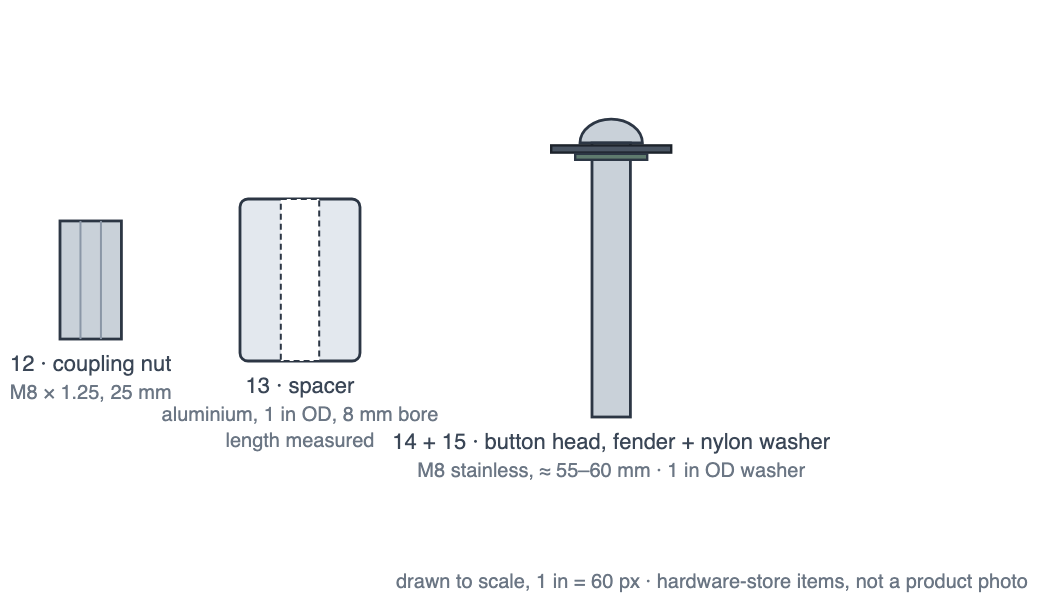
| 12 | M8 × 1.25 coupling nut, 25 mm long, stainless | 10 | Threaded onto the factory studs, 5 per side — count confirmed on the van | hardware store |
| 13 | Aluminium unthreaded spacer, 8 mm / 5/16 in ID, 1 in OD, length measured (owner build used 1.35 in) | 10 | Between the coupling nut and the side rail. A catalog spacer in a stock length replaces the cut pipe | McMaster-Carr, ~$1–2 ea |
| 14 | M8 × 1.25 button-head cap screw, stainless, length = spacer + 3 mm wall + 12 mm engagement (≈ 55–60 mm) | 10 | Down through the side rail's back slot into the coupling nut | hardware store |
| 15 | M8 fender washer 1 in OD + M8 nylon washer | 10 + 10 | Under the button head, bridging the 9/16 in back slot | hardware store |
| E · Panel retention | ||||
| 16 | Solar end clamps + mid clamps for a 40 mm frame, 5/16-18 hardware | 8 end + 2 mid (a 12-pack) | Into the panel-rail slots at the positions above. Pick a 5/16-18 kit so the nut is a P1007 channel nut; an M8 kit needs Unistrut's metric nut instead. Confirm the positions against the Jinko manual's clamp zone before ordering | ~$3–4 per clamp |
| 17 | Unistrut P1007 5/16-18 channel nut with spring | 10 | One per clamp | per family page |
| F · Isolation, ends, grounding | ||||
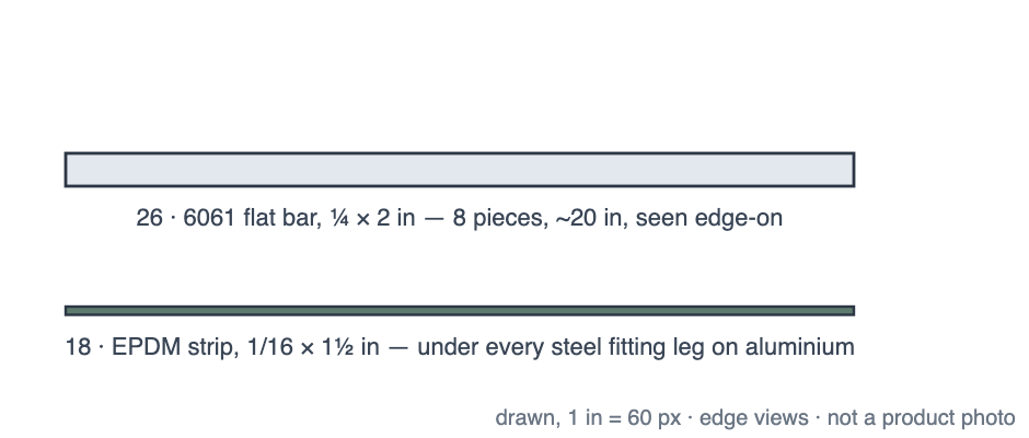
| 18 | EPDM strip, 1/16 × 1½ in, ~12 ft + nylon washers under bolt heads | 1 roll | Under every steel fitting leg on aluminium channel. Cheap insurance against the dissimilar-metal joint; unnecessary if the fittings come in aluminium | ~$15 |
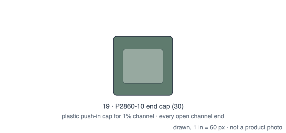
| 19 | Unistrut P2860-10 end cap, 1⅝ in | 30 | 4 side-rail ends, 10 crossbar ends, 6 panel-rail ends, 10 upright tops | ~$0.50 ea |
| 20 | Module grounding lugs / bonding jumpers | per one-line | Selected in the electrical sign-off, not here | — |
| 21 | Front fairing | 1 | A flat aluminium plate on three tabs at the panel-rail ends and four stays under C0. Drawn, with its own parts list (F1–F11), on the fairing page. Required by the roof-frame page. Revised 2026-09-28: it was listed as a catalog deflector mounted to C0; the universal ones found stop around 52 in wide. | not priced |
Everything with a price on it comes to roughly $260 before the channel and the clamps. The aluminium channel quote decides the real number, and it will be several times that. Get it first — for 135 ft, cut to the list above — and ask on the same call whether P2484 in aluminium is a stocked line for them or a special order, because that answer decides whether line 18 is needed at all.
Weight, since payload is the constraint on this build. 111 ft of aluminium P1000T at the catalog section area (0.555 in²) is about 72 lb; ten EG P2484s are 13 lb; fittings, nuts, bolts, clamps and gutter hardware add roughly 12 lb. Call the rack 100 lb, so ~250 lb on the roof with the three modules. The same rack in steel channel would be ~230 lb on its own, which is the whole argument for the quote.
What to buy — the A/C and fan frames
the internal reinforcement from the appliance page, made from the same family so it is one order · the joint to the roof bows is still the open item
Step-by-step, part-by-part, for a first metal build: building the A/C and fan frames →
Each appliance gets a flat rectangle of the same 1⅝ in channel under the roof skin: two fore-aft members that reach from one factory roof bow to the next and sit under the appliance's outboard bearing pads, and two transverse headers framing the opening front and rear. A ¼ in aluminium flat bar ring on top of the frame, against the roof skin, is what the A/C's gasket and pads bear on and what the fan's flange screws bite into. The stack under the skin is 0.25 + 1.625 = 1.9 in deep, inside the 2 in ceiling build-up the cross-sections already budget, so it costs no headroom. The Velit's four M8 rods and lower bracket clamp through that whole sandwich; its permitted mounting-thickness range is checked against roof + bar + channel before anything is cut.
| # | Part | Qty | Where it goes | Displayed price |
|---|---|---|---|---|
| 22 | P1000T aluminium — fore-aft members | 4 × ~36 in | Bow pitch plus overlap, cut after the pitch is measured. Two under the A/C pad lines, two beside the fan | in the channel quote (~22 ft) |
| 23 | P1000T aluminium — headers | 2 × ~32 in (A/C) + 2 × ~22 in (fan) | Framing each opening front and rear, between the fore-aft members | |
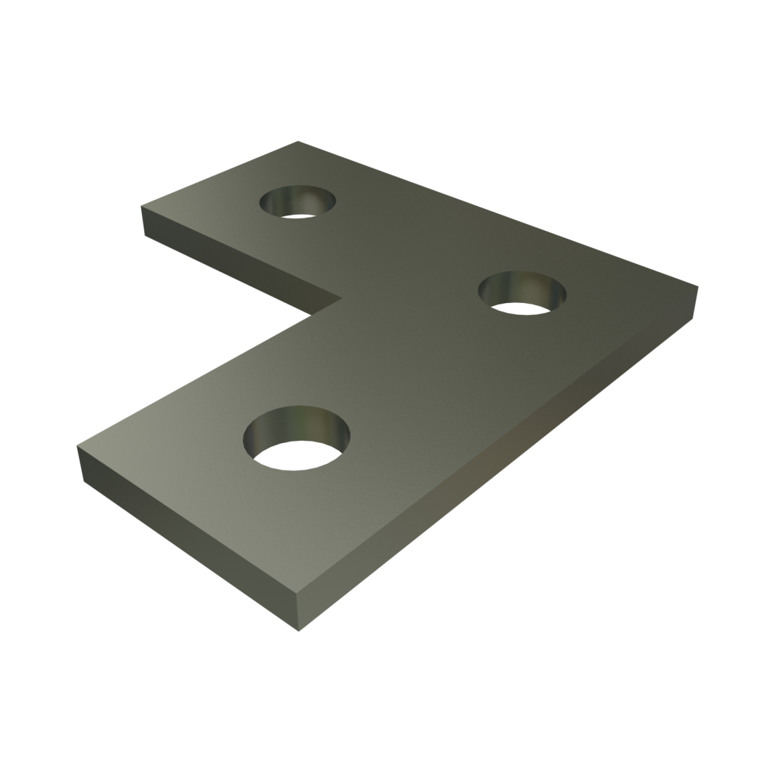
| 24 | 3-hole 90° flat corner plate for 1⅝ in strut (same fittings family as P1026 — take the number off the distributor's fittings page) | 8 | The four in-plane corners of each frame, on the slot faces, 3 × ½-13 bolts and P1010 nuts each | ~$3–5 ea |
| 25 | P1010 nuts + ½-13 × 1 in bolts | 24 + 24 | For the corner plates — add to lines 7 and 8 | — |
| 26 | 6061 aluminium flat bar, ¼ × 2 in, ~14 ft | 8 pieces, ~20 in | A ring around each opening, cut to length and drilled on the bench to the appliance's own template. This frame was always allowed to be fabricated; the roof rack was not | metal supplier, ~$60 |
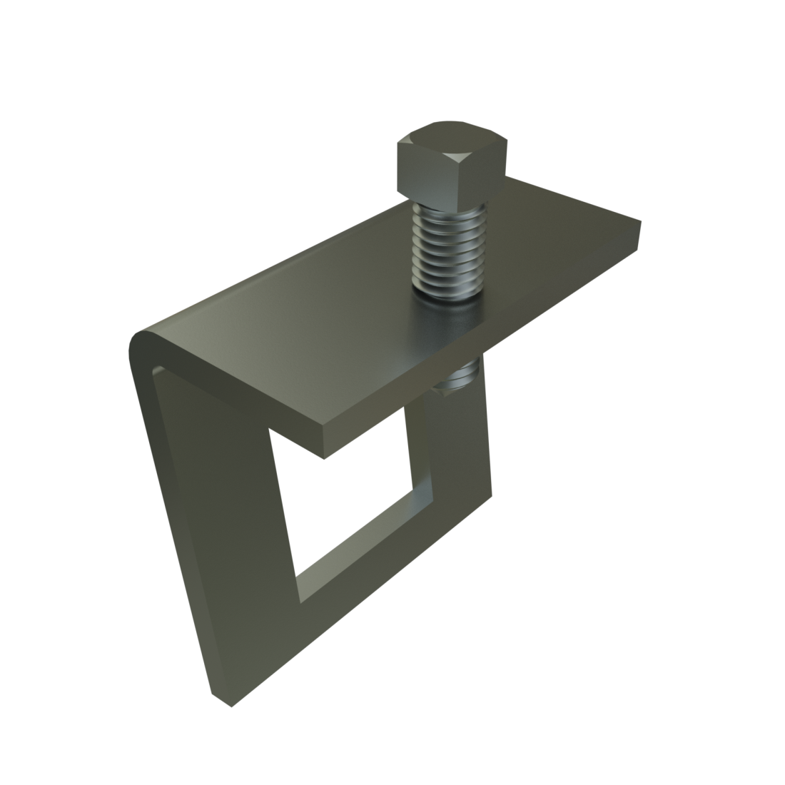
| 27 | Bow attachment — decided at the van. Either a Unistrut window / flange beam clamp (P1796S family, for a flange up to ⅞ in) if the bow has a usable flange, or ½ in through-bolts with crush sleeves if inspection permits drilling a bow | 8 | Two per fore-aft member end. This is the joint the appliance page calls unverified; it does not get bought until the bow section has been seen | ~$5–10 ea |
| 28 | Velit's own M8 rods, lower bracket, gasket and pads · MaxxFan's own screws and sealant | supplied | Never substituted, never torqued to a rack figure | in the box |
What the tape measure changes
the delivery-day measurements, and which line on this page each one moves
- Gutter line to gutter line. The layout needs ≥ 85 in; the drawing assumes 86. Every inch under 85 comes out of the 3.4 in curb-side margin first, then the 0.9 in mid-clamp gap. Below ~84 in the two-column layout does not fit and P3 goes transverse behind P2 instead — a different page. Moves: line 2 (crossbar length), and the whole plan if it fails.
- Roof crown above the stud base. Assumed 3.7 in. Under 3.7 the stack stays as drawn (the upright cannot go much below 7 in — the P2484 leg and the through-bolt need the room) and the spacer is what shortens. Over 3.7, the upright grows inch for inch. Moves: line 4, line 13.
- Stud count, pitch, thread projection, both sides. Sets the side-rail length and the count on lines 12–15. If a stud lands within 2 in of an upright station, shift the upright, not the stud.
- Both rear gutter ends, photographed. The drain filter in the owner build decides where the last stud and C4 can land. Moves: C4's station and the side-rail length.
- Roof bow pitch and section. Sets lines 22–23 and decides line 27 outright. Nothing on the frames is cut before this.
- The fan model. The 24 × 30 reserve is a placeholder. The real body, flange and lid arc replace it; C3 and C4 move if the reserve grows. The A/C and the fan can also swap ends without changing the rack family — the free bands shift by about 6 in and C1 and C3 shift with them.
- The Jinko installation manual's clamp zone. Confirms or moves the ten clamp positions along the rails. It changes nothing structural.
- One more thing the drawing shows. The Velit body as placed overhangs the 71.65 in flat roof panel on the curb side by about 3.4 in — its opening stays in the flat zone, its outboard pads do not. The curb-side fore-aft frame member lands near the cant rail, which is the right structure; the roof shoulder under those pads is checked for slope against the manual's 15° limit.
Building it, in this order
the layout-specific steps that sit inside the five-stage build order
- Bench one crossbar with its two uprights first. Two P2484s, two P1026s, one 86 in bar. Square it, confirm every channel nut is turned under the lips, record the torque the distributor gives for aluminium channel. That one assembly proves the corner before four more are made.
- Side rails on, one stud at a time. Coupling nuts first, spacers, then the rails, then check the gutters still drain.
- Five crossbar assemblies at their stations, P2484 legs onto the side rails. Check crown clearance with someone standing on the crossbars, not with the van empty.
- Three panel rails across the crossbars, one bolt at each of the 15 crossings. Sight down each rail for straightness before the clamps go on.
- Clamps at the ten positions, then glass. P1 and P2 first (they set the driver-side rail), P3 last. Lift by the frame. Mid clamps at 66 and 107.5 go on after both neighbouring panels are down.
- End caps, EPDM checks, cable clips, the fairing on the panel-rail ends and C0. Then the loaded-miles re-torque from stage 5.
Status: geometry and quantities for the decided layout, drawn from datasheets on an assumed envelope. Supersedes nothing — it sits between the hardware page and the build order, and it is the page the distributor gets. Drawn and written by Maple, 2026-09-17.