← back to the build document · building the roof rack · the standard brackets · the rack for the lengthwise layout · the design history · mounting the a/c & fan · building the a/c & fan frames · the interior frame · the parts list · the build manual · the solar book, distilled · projected dimensions
The roof frame
The Zevo's roof is a weather barrier, not a bearing surface — the centre is thin and the van is short on roof supports, and the 2024 build predates the load-bearing roof GM made standard in October 2025. So the load goes to the roof edge, down both sides, and nothing rests on sheet metal. This page is the design case for that. It is not a construction method any more.
Two things changed since this page was first written. The A/C and the fan came off the exterior structure — they seal at roof level and an internal frame carries them, so the rack now carries solar only. And as of 2026-09-16 the supports are built from ordinary catalog strut fittings rather than plates and gussets cut to order: the standard brackets →.
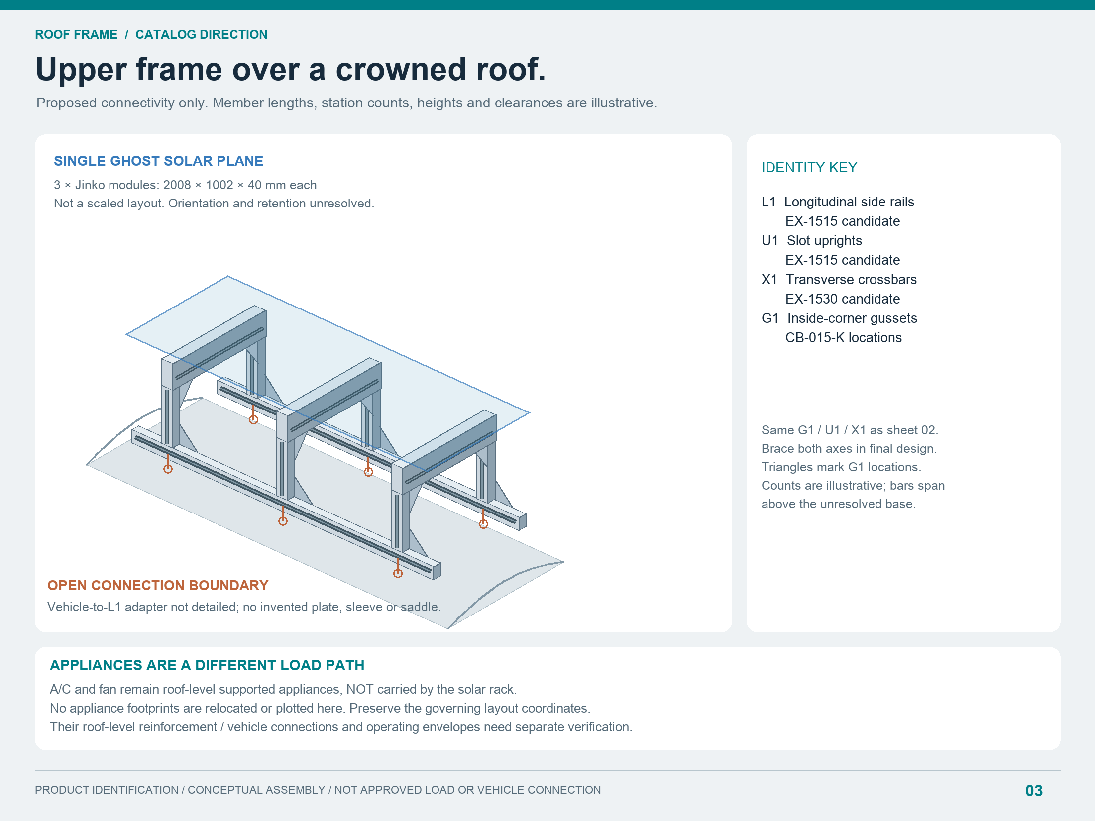
The design rule everything else follows from
No equipment weight is carried by the roof skin — including the A/C and the fan. That is the rule. What changed is where each load goes instead: solar to a rack at the roof edge, appliances to an internal frame. Two chains, not one structure.
- Crossbars around an opening are not enough. A rooftop A/C's feet and its clamping mechanism need a continuous load path into structure. Framing an opening is not the same as supporting the appliance — which is why that job left the rack entirely.
- The fan needs the same thing — its mounting flange and screw loads land on real backing, not on unsupported sheet.
- Where that support lives has changed. It is not a curb on the exterior rack any more. The A/C and the fan seal at roof level and an internal reinforcement frame under the roof carries them into verified vehicle structure: mounting the A/C and the fan →. Gaskets, sealant and flashing still seal and still carry nothing.
- A/C and fan stay at opposite ends, with room for the fan lid to open fully and for A/C airflow and service access — and the rack's crossbars have to stay clear of all of it.
- Load path, top to bottom — two separate ones now. Solar: panels → approved retention hardware → crossbars → risers → whatever catalog base kit attaches to the vehicle → the vehicle's edge structure. Appliances: A/C or fan → supported mounting surfaces → internal backing and beams → vehicle structure. Neither chain is verified end to end. The solar chain has no confirmed product at the vehicle; the appliance chain lands on factory roof bows that carry no published rating.
What the forum build actually documents
source: BrightDrop Forum, roof rails / racks — thread 188, posts #15 and #24 → (FumelessCamper)
M8-1.25 studs already protrude above the rain gutter on both roof edges from the factory. One owner built onto them with no drilling, no adhesive and no VHB. This is recorded as evidence that the roof edge is where builders put load on this platform — it is a historical owner example, not the method being followed. Two of its four items below are parts cut to length, which the no-fabrication rule excludes:
- Aluminium unistrut — one 10 ft rail per side, running fore-aft along the gutter. This is the side rail, not the crossbar. Crossbars are a second layer above it.
- M8 × 1.25 coupling nuts, 25 mm long — threaded onto the factory studs, five mounting locations per side.
- Spacers cut from 1 in nominal schedule-40 aluminium pipe, 1.35 in long — present in the finished install and easy to leave out of a summary.
- M8 × 1.25 button-head bolts, installed from above, with fender washers under the heads.
The roof edge sits below the crown — so height has to come from somewhere
The rain gutter is lower than the roof crown. Anything bolted flat to it therefore sits below the surface it has to clear, and a bar laid straight across would land on the middle of the roof — the one thing this whole design exists to avoid. The height has to be bought back deliberately.
- It comes from a braced upright — and the bracing is now a catalog part. The old answer was a pedestal of cut plates and gusset cheeks. That is retired: a gusseted strut fitting like P2484 is the braced corner, stocked, and the upright between the two fittings is just a member cut to length.
- The rise is a measured output. Roof crown above the attachment line, plus clearance for suspension movement, chassis flex and loaded deflection. The fitting's own leg length matters too — the P2484 cut sheet gives both legs as 4″ (102 mm), so a riser shorter than that cannot take a full bolt pattern.
- Do not buy the height with fastener stack. Stacked coupling nuts or a long exposed bolt acting as a post puts bending straight into a factory stud — the exact failure mode the source thread warns about.
- Keep it as short as the roof allows. Every inch of rise increases the bending moment at the attachment points. If the required height turns out to be substantial, that is a signal that the configuration is wrong, not a reason to stack height.
Raising the crossbars above the roof crown — the corner that does it
The height comes from an upright between two fittings, and the bracing comes from the fitting itself. Here is that corner in three states — assembled, exploded, and a section through the fastener:
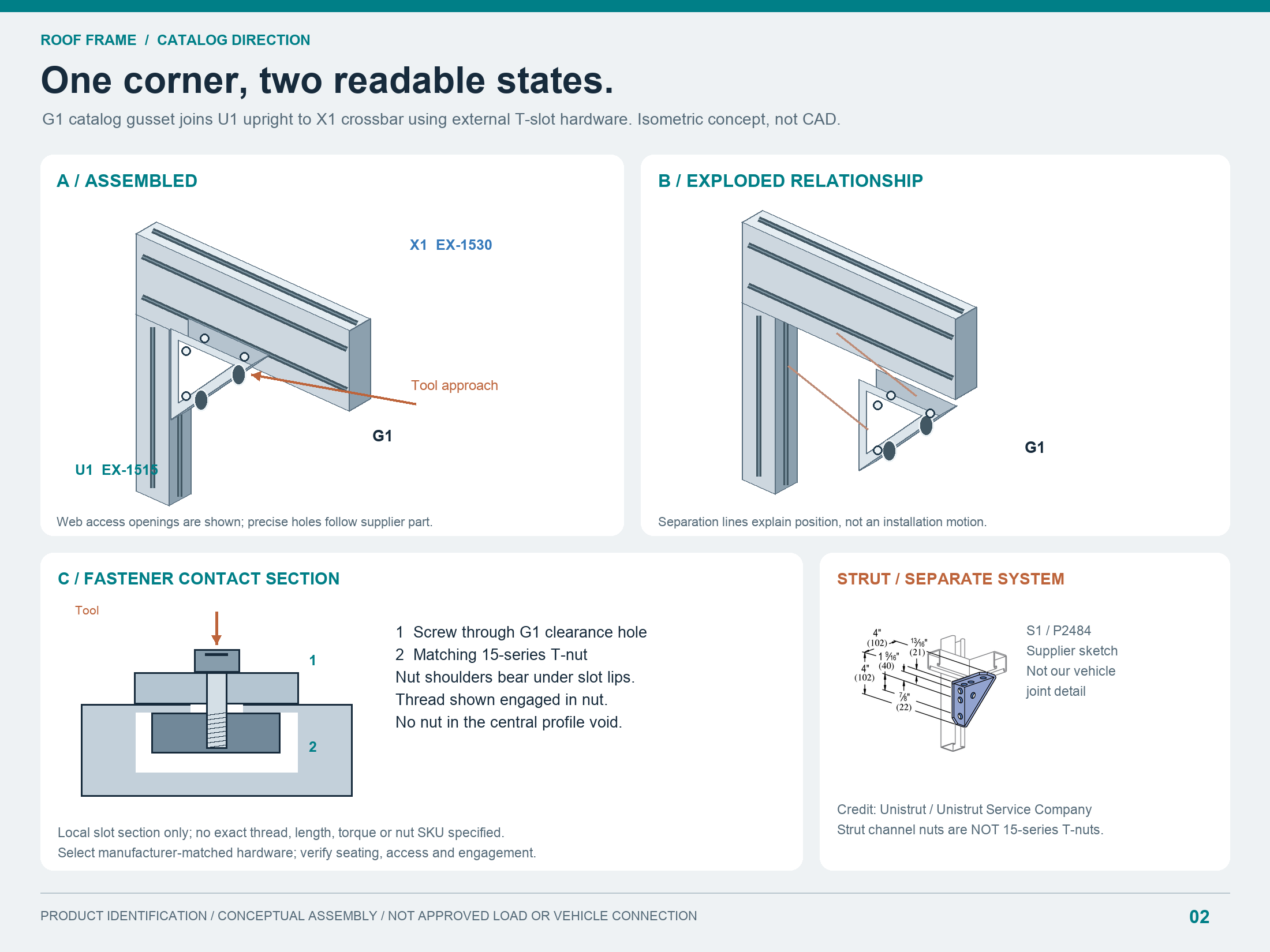
The fabricated pedestal that used to answer this question is archived with the rest of the retired drawings: the retired roof-frame concepts →.
The weight delta nobody has closed yet
- The documented rails carried 72 lb for 1,170 W — flexible panels, pre-bent and tensioned, deliberately light. This build puts 148.8 lb of glass on a comparable edge geometry, before the rack hardware itself. More than double. That an owner's rails worked at 72 lb establishes nothing at 149 lb, and it is one of the numbers a supplier has to rate against rather than something to reason around.
- Not a counterexample — a proposal: another owner (madude) has proposed roughly 411 lb of roof- and side-mounted panels on a Zevo 400 — six Longi 550 on the roof and ten Aiko 440 on hinged side walls — but describes the project as still largely in CAD. This does not establish the capacity of the gutter studs or validate this rack. It also assumes a purpose-built frame with wind deflectors, not panels bolted flat to a strut.
- Direct-thread caution from the same thread: the studs are fine "as long as you are not putting big bending loads" on them. Long unsupported spans between attachment points is precisely how you create that.
- Highway wind loading is a live load on the same joints and is not in the 148.8 lb figure at all. A front fairing closing the gap under the leading panel is a required line item, not a nicety — it was the advice one owner gave another, and it was adopted.
What the thread does not establish
- Bolt length, washer dimensions, channel specification or tightening torque.
- Any rated capacity for the gutter studs, individually or as a set — and no GM position on using them for this.
- Crossbar span, spacing or usable positions for glass panels, which are a point-loaded, rigid, much heavier case than the flexible panels in the example.
- Appliance-specific mounting requirements for the chosen A/C and fan, which drive the internal reinforcement — and the rack clearances around it.
- Attachment capacity at the gutter studs, which is the one genuinely open item in the chain: stage 1 of the build order →
Status: a design case and an owner-built precedent, not an engineered or approved mounting system — and no longer a construction proposal. The drawings on this page are superseded; the requirement they illustrate is not.
The measurements that unblock the parts list
- Gutter studs: count, centre-to-centre spacing and exposed thread projection, both sides. This is what a manufacturer needs before it can answer a fit question at all.
- Across the van: distance between the two gutter stud lines. Decides whether any fixed-width catalog crossbar kit is usable.
- Roof crown height above the gutter mounting lines. Sets how tall the frame has to stand to clear the roof without touching it — the cross-section above is exactly this dimension.
- Both rear gutter ends, photographed. There is a drain filter at the rear gutter end in the documented build; it decides where the last attachment point can land.
- A/C and fan footprints, flange dimensions and clamp requirements from their own instructions. Those size the internal reinforcement and the roof openings, and the openings set which crossmembers can run straight through above them.
How the rack actually gets chosen
Everything above is the design case — why the load goes to the roof edge and what it has to carry. The parts and the order of work are on the other two pages: the standard brackets → and the build order →
That page also carries the service-history evidence from an owner build on this platform with 10,000 reported miles on it — fastener retention, why mechanical clearance and panel ventilation have to be sized as separate requirements, and the fact that its cell failure was visible only by climbing up and looking.